Impedance (Z), in electrical devices, refers to the amount of opposition faced by direct or alternating current when it passes through a conductor component, circuit or system.

Contents
1 The definition of an impedance
2 What causes impedance?
3 How to find input impedance?
4 What is an impedance test?
5 How can PCB impedance be controlled?
The definition of an impedance
Impedance is the sum of the resistance and reactance of an electrical circuit expressed in Ohms. The resistance being the opposition to current flow present in all materials.
At the physical level, simplifying many things: the resistance is caused by the collisions of the electrons with the atoms inside the resistors. the impedance in a capacitor is caused by the creation of an electric field. the impedance in an inductor is caused by the creation of a magnetic field.
To find the output impedance the output voltage is measured first with no load resistor, then with a fixed load (purely resistive). To measure the input impedance over a complete spectrum of frequencies, use the following circuit: The input is a constant current source, its value set to 1amp.
An impedance tester is an electronic device that qualified technicians use to. Measure the level of resistance in the earth return circuit and. Make sure it is low enough to allow enough current to flow through the circuit and operate a protective device when a fault is detected.
How can PCB impedance be controlled?
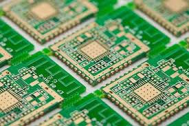
A PCB manufacturer can control the impedance through spacing and dimensions of the circuit board traces. Typically, printed circuit boards are available with three levels of impedance control service.
