Posted: May 14, 2022 by: Bonnie
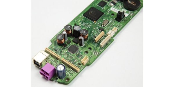
Printed circuit board( PCB ) is an important electronic part, support for electronic components, and a carrier for the electrical connection of electronic components. Because it is made using electronic printing, it is called a "printed" circuit board.
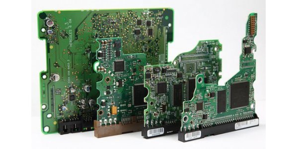
According to the rigidity and flexibility of the raw material, printed circuit boards are divided into two categories: rigid copper-clad laminate and flexible copper clad laminate.
According to different reinforcing materials, printed circuit boards can be divided into four categories: phenolic paper substrate, epoxy glass fiber cloth substrate, composite substrate (CEM series, etc.), and special material substrate (ceramic, metal base, etc.)
AiPCBA is engaged in the following businesses: flexible PCB, custom PCB, prototype PCB, turnkey PCB assembly, quick turn PCB assembly, electronic PCB assembly, small batch PCB assembly, etc. You can learn more about our PCB manufacturing capabilities.
1.Phenolic Paper Substrate
Phenolic paper substrate (commonly known as, cardboard, plastic board, V0 board, flame retardant board, red-letter CCL, 94V0, TV board, color TV board, etc., is the most widely used, there are many famous brands, including Kingboard (KB characters) ), Changchun (L character), Doosan (DS character), Changxing (EC character), Hitachi (H character), etc. It uses phenolic resin as a binder.
2.Epoxy Glass Fiber Cloth Substrate
Epoxy glass fiber cloth substrate (commonly known as the epoxy board, glass fiberboard, fiberboard, FR4), epoxy glass fiber cloth substrate is a kind of epoxy resin as adhesive and electronic grade glass fiber cloth as reinforcement material substrate. Its bonding sheet and inner core thin copper-clad laminate are important base materials for making multi-layer printed circuit boards. The working temperature is high, and its performance is less affected by the environment. In terms of processing technology, it has great advantages over other resin glass fiber cloth substrates. This type of product is mainly used for double-sided PCB, which is also about twice as expensive as the phenolic paper substrate, and the commonly used thickness is 1.5mm.3.Composite Substrate
Composite substrate (commonly known as powder board, etc., the CEM-1 board is also called 22F in some places in China) It mainly refers to CEM-1 and CEM-3 composite base copper clad laminates. It uses wood pulp fiber paper or cotton pulp fiber paper as the core reinforcement material, and glass fiber cloth as the surface reinforcement material, both of which are impregnated with a copper-clad laminate made of flame retardant epoxy resin, which is called CEM-1. The copper-clad laminate made of glass fiber paper as the core material reinforcement and glass fiber cloth as the surface reinforcement material, both dipped in flame-retardant epoxy resin, is called CEM-3. These two types of copper-clad laminates are the most common composite base copper clad laminates. This type of sheet is cheaper than the FR4 type sheet.4.Special material substrate
(1)Aluminum SubstrateThe aluminum substrate can minimize the thermal resistance, making the aluminum substrate have excellent thermal conductivity, and the biggest advantage of the aluminum substrate is that it can carry higher currents. The core technology of the aluminum substrate is the intermediate insulating layer material, which mainly plays the role of bonding, insulation, and heat conduction. The aluminum substrate insulation layer is the largest thermal barrier in the power module structure. The better the thermal conductivity of the insulating layer, the more conducive to the diffusion of heat generated during the operation of the device, and the more conducive to reducing the operating temperature of the device, so as to achieve the purpose of increasing the power load of the module, reducing the volume, prolonging the life, and improving the power output. In addition to good thermal conductivity, it must also have high-voltage insulation capabilities.
The copper substrate is the most expensive metal substrate, and its thermal conductivity is many times better than that of aluminum and iron substrates. The circuit layer of the copper substrate is required to have a large current carrying capacity, so thicker copper foil should be used, with a thickness of generally 35μm~280μm. The thermal conductive insulating layer is the core technology of the copper substrate. The core thermal conductive component is composed of aluminum oxide and silicon powder and epoxy resin-filled polymer. It has the ability to resist thermal aging, small thermal resistance, and excellent viscoelastic properties.
(3)Ceramics Substrate
Ceramic substrates, due to their heat dissipation performance, current carrying capacity, insulation, thermal expansion coefficient, etc., are much better than ordinary glass fiber PCB boards, so they are widely used in high-power electronic modules, aerospace, military electronics, and other products.
5.Glass transition temperature (Tg)
Tg: glass transition temperature, which is the glass transition temperature (which has the greatest impact on vias). The glass transition temperature is a characteristic of the polymer. It refers to the temperature at which the resin changes form from hard (glassy) to soft (rubbery). The printed circuit board must be flame-resistant, it cannot burn at a certain temperature, it can only soften. The temperature point at this time is related to the dimensional stability of the PCB board. The higher the TG value, the better the temperature resistance of the PCB.
Ordinary Tg value: 130~140℃.
Medium Tg value: 140~150℃.
High Tg value: greater than 170℃ (PCB board with more than 8 layers must use high Tg board).
6.High-frequency PCB
High-frequency circuit boards refer to special circuit boards with high electromagnetic frequencies, which are used for PCBs in the fields of high frequency (frequency greater than 300MHZ or wavelength less than 1 meter) and microwave (frequency greater than 3GHZ or wavelength less than 0.1 meters).
It is a printed circuit board produced by using part of the process of ordinary rigid circuit board manufacturing method or special processing method on microwave substrate copper clad plate. Generally speaking, a high-frequency board can be defined as a circuit board with a frequency above 1GHz.
Popular high-frequency PCB material brands are as below.
Taconic: TLX series, TLY series, etc.
Panasonic: Megtron4, Megtron6, etc.
Isola:FR408HR, IS620, IS680, etc.
Nelco:N4000-13, N4000-13EPSI, etc.
TUC:Tuc862, 872SLK, 883, 933, etc.
How to select the PCB Material?
Designing a printed circuit board (PCB) is a routine task for most electronics engineers. Despite years of PCB design experience, creating a high-quality performance-driven PCB design is not easy. There are many factors to consider and board material is one of them. The basic materials used to manufacture the PCB are very important. Before fabrication, the properties of the material in various aspects such as flexibility, temperature resistance, dielectric constant, dielectric strength, tensile strength, adhesion, etc. must be considered. The performance and level of integration of the circuit board are completely dependent on the materials used.
(1)Dielectric constant
The dielectric constant must be small and stable, usually the lower the better. The transmission rate of the signal is inversely proportional to the square root of the dielectric constant of the material. A high dielectric constant can easily cause signal transmission delays. The lower the dielectric constant, the faster the signal transmission.
The dielectric loss must be small, which mainly affects the quality of signal transmission. The smaller the dielectric loss, the smaller the signal loss, and the stronger the ability to reach the receiving end under the same length of the signal line.
The commonly used PCB medium is FR4 material, and the relative dielectric constant of air is 4.2-4.7. This dielectric constant will change with temperature. In the range of 0-70 degrees, the maximum change range is 20%. The change of the dielectric constant will cause a 10% change in the line delay, and the higher the temperature, the greater the delay.
The dielectric constant also varies with the frequency of the signal, the higher the frequency, the smaller the dielectric constant. The transmission speed of the inner layer signal in the general FR4 material PCB board is: 180ps/inch(1inch=1000mil=2.54cm).
AiPCBA is providing PCB manufacturing and PCB assembly services. We have clients from different industries all over the world. We can provide services from PCB layout to PCB prototyping, volume manufacturing, PCB assembly, and electronic box assembly. Our Printed Circuit Boards are used in robotics, medical, automotive, communications, industrial, and consumer electronics. Well suited to our client’s requirements in terms of cost-effectiveness, quality, delivery, and any other requirements. We can offer all kinds of PCB materials to meet our customers. Feel free to ask about our PCB price and use AiPCBA online quote platform to check your design cost of PCB.