Pick and Place File
Posted: May 14, 2022
By: Bonnie
Pick and Place File is commonly known as (SMT coordinate file). When pcb carries out smt, it needs a specific placement location to be able to place normally. At this time, you need to go to pick and place file. AiPCBA provides SMT service, users only need three files: Gerber file, pick and place file, BOM file.
The following describes how the commonly used Altium and Easyeda pcb design software exports the pick and place file.
Export pick and place file from Altium

detailed steps:
Step 1: Set coordinate 0
Edit-> Origin-> Settings; the default setting origin is in the lower left corner
Step 2:
Click File »Assembly Outputs» Generates pick and place files from a PCB.
Step 3: Set the format and unit
Choose CSV format and metric (or English)-> OK (see step 3 after the dialog box disappears)
Step 4: Find the export file storage directory
You can use the query function to find the file directory or version. Manually open the directory where the PCB file is stored.
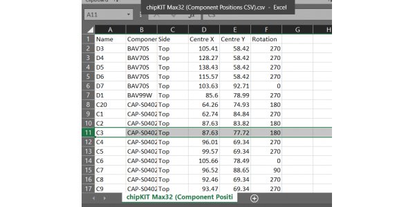
Step 5: Open or view the output file
Here is a CSV file named Quan Pick Place for xxx that was just exported.
Briefly explain the purpose of the most commonly used fields
Designator component label; Footprint package; Mid X element midpoint X coordinate; Mid Y element midpoint Y coordinate;
Layer component layer; Rotation device rotation angle; Comment model;
Export pick and place file from Easyeda

The corresponding unit format needs to be set for export: This file support two units “mm” and “mil”, it is following the PCB unit setting.
More resources:
Do you have any questions about the above-mentioned? Contact us now, we will reply to you soon.
Is the article useful to you?
No
Yes(
9
)
9
681
1
Share to: