Reflow Soldering Structure and Welding Curve
Posted: May 14, 2022
By: Bonnie
1. Total power switch: I is connected to the power supply; O is disconnected from the power supply.
 2. Color display: display operation information, which is convenient for the operator to understand the current working status and accurately display the current parameters of the machine.
3. Keyboard: Enter information to complete control of the machine.
4. Tri-color lamp: Shows the working status of the machine.
Red: The machine is in the A]1ARM state, the machine will not work at this time, and the fault must be eliminated.
Yellow: WARNING state or NEW JOB cut.
Green: The machine is in a normal state.
For example, the temperature setting in a temperature zone is 200 °C, the normal range is set to 15 °C, the alarm range is set to 40 °C, the current temperature is 185~215 °C, the green light is on, the current temperature is 160~185 °C or Bright yellow light when 215~240°C, red light when the current temperature is lower than 160°C or higher than 240°C.
5. RESET button: Whenever you press the “E-STOP” button and then restart the machine, you need to press the “RESET” button to initialize the furnace; when the machine starts production, you need to press the “RESET” button.
8.H00DKEY: used for lifting and lowering the furnace H00D.
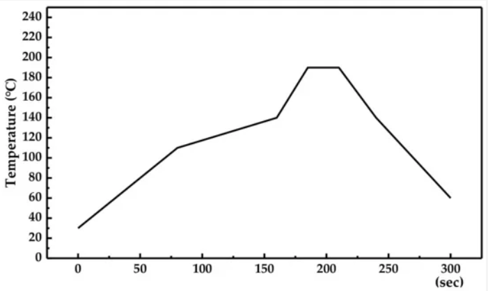
Reflow soldering curve
Stage 1: The temperature must rise at a rate of approximately 3 ° C per second to limit solvent boiling and flying reduction in tin tones. If the temperature rises too fast, the solvent will boil, causing the metal powder in the tin cyan to splash everywhere, so that after cooling and solidification, small tin beads are formed, which affects the electrical properties of the product. In addition, there are some electronic components that are sensitive to temperature. If the external temperature of the component rises too fast, it will cause the component to burst.
Stage 2: The flux is active, the chemical cleaning action begins, and the same cleaning action occurs for both the water-soluble flux and the no-clean flux, except that the temperature is slightly different. At this point, the flux in the solder paste will quickly destroy the surface oxide of the solder material and the solder pad surface of the PCB pad, so that the soldered end of the component is in full contact with the PCB pad.
Stage 3: The temperature continues to rise, and the solder grain is first melted separately and begins the “lighting grass” process of liquefaction and surface suction. This covers all possible surfaces and begins to form solder joints.
Stage 4: This stage is most important. When a single solder particle is completely melted, it combines to form a liquid tin, at which point the surface tension begins to form the surface of the solder fillet. If the gap between the component leads and the PCB pads exceeds 4 mils, it is highly likely that the pins will be separated from the pads due to surface tension, resulting in an open circuit point.
3. Keyboard: Enter information to complete control of the machine.
4. Tri-color lamp: Shows the working status of the machine.
Red: The machine is in the A]1ARM state, the machine will not work at this time, and the fault must be eliminated.
Yellow: WARNING state or NEW JOB cut.
Green: The machine is in a normal state.
For example, the temperature setting in a temperature zone is 200 °C, the normal range is set to 15 °C, the alarm range is set to 40 °C, the current temperature is 185~215 °C, the green light is on, the current temperature is 160~185 °C or Bright yellow light when 215~240°C, red light when the current temperature is lower than 160°C or higher than 240°C.
5. RESET button: Whenever you press the “E-STOP” button and then restart the machine, you need to press the “RESET” button to initialize the furnace; when the machine starts production, you need to press the “RESET” button.
6. E-STOP button: Press this button to interrupt all power when an emergency occurs, only the computer continues to work.
8.H00DKEY: used for lifting and lowering the furnace H00D.
9. Track: used for PCB transmission, there are two kinds of chain nets and chains. The chain net produces one side and the chain produces the opposite side.
Reflow soldering curve
Stage 1: The temperature must rise at a rate of approximately 3 ° C per second to limit solvent boiling and flying reduction in tin tones. If the temperature rises too fast, the solvent will boil, causing the metal powder in the tin cyan to splash everywhere, so that after cooling and solidification, small tin beads are formed, which affects the electrical properties of the product. In addition, there are some electronic components that are sensitive to temperature. If the external temperature of the component rises too fast, it will cause the component to burst.
Stage 2: The flux is active, the chemical cleaning action begins, and the same cleaning action occurs for both the water-soluble flux and the no-clean flux, except that the temperature is slightly different. At this point, the flux in the solder paste will quickly destroy the surface oxide of the solder material and the solder pad surface of the PCB pad, so that the soldered end of the component is in full contact with the PCB pad.
Stage 3: The temperature continues to rise, and the solder grain is first melted separately and begins the “lighting grass” process of liquefaction and surface suction. This covers all possible surfaces and begins to form solder joints.
Stage 4: This stage is most important. When a single solder particle is completely melted, it combines to form a liquid tin, at which point the surface tension begins to form the surface of the solder fillet. If the gap between the component leads and the PCB pads exceeds 4 mils, it is highly likely that the pins will be separated from the pads due to surface tension, resulting in an open circuit point.
More resources:
Do you have any questions about the above-mentioned? Contact us now, we will reply to you soon.
Is the article useful to you?
No
Yes(
6
)
6
458
1
Share to: