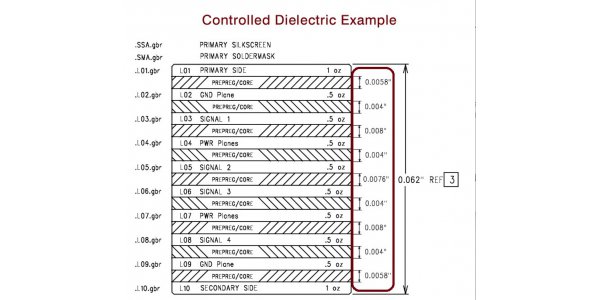
The control dielectric refers to the material which records various processing information in the form of instructions, such as the technological process, process parameters and tool movement of parts processing. These information are input into the CNC device to control the CNC machine tool to cut the parts. Such as perforated paper tape, magnetic tape, magnetic disk, magnetic bubble memory and so on. Controlled impedance, the conductor in the circuit board will have a variety of signal transmission, in order to improve its transmission rate, the frequency must be increased. If the circuit itself due to etching, stack thickness, wire width and other factors, the impedance value will change and the signal will be distorted. Therefore, the impedance value of the conductor on the high-speed circuit board should be controlled within a certain range, which is called "impedance control”.

Controlled impedance means that the printed circuit board is manufactured so that the impedance of the circuit is within a certain percentage of the specified value. The controlled medium only specifies that the dielectric constant of PCB substrate is within a certain percentage of a certain value. A controlled impedance board usually has a controlled dielectric substrate, but the reverse is not necessarily true. Having a control impedance means that the PCB is manufactured so that the trace is within a certain percentage of the specified value. Controlled dielectrics only specify that the permittivity of PCB substrate is within a certain percentage of a certain value. A controlled impedance board usually has a controlled dielectric substrate, but the reverse is not necessarily correct. See how to calculate controlled impedance and get further information about high controlled impedance on AiPCBA.

The sum of impedances is expressed as resistance. The resistance in all materials that is opposite to the current. Reactance is the reaction to current produced by the interaction between the inherent capacitance and inductance of a conductor and the changes of voltage and current. There is no reactance in the direct circuit, and the resistance of the copper conductor is usually negligible. However, reactance and impedance can become very important in high-speed AC circuits (circuits with sharp changes in voltage and / or current). This is critical to the functionality of the design, as the impedance changes from transmitter to receiver along the signal path can affect power transmission efficiency and signal integrity. Although the speed of a circuit is usually expressed in terms of the frequency of the waveform: the key issue is the speed at which the voltage and / or current needs to be changed.
In determining impedance control requirements, typical design considerations include the strength of the signal involved, the sensitivity of the circuit to noise and signal distortion, the criticality of signal timing, and the voltage and / or velocity current that the signal source is trying to force. The design considerations for setting the conductor impedance are usually the output impedance of the transmitter and the input impedance of the receiver. The impedance of other conductors (ie. coaxial cables) in the circuit path also needs to be considered. It is necessary to determine and consider the acceptable range (tolerance) of impedance during the design phase and when specifying PCB parameters. In many cases, it is sufficient to use a software model to determine the expected impedance for a specific dielectric material and spacing, and then to require compliance with these parameters during PCB manufacturing. This is what we call "controlled dielectrics". For more critical applications, you need to specify the "controlled impedance" and provide the actual impedance requirements of the conductor, which we will fine tune to meet. Impedance requirements must be specified in terms of layer and conductor width.
