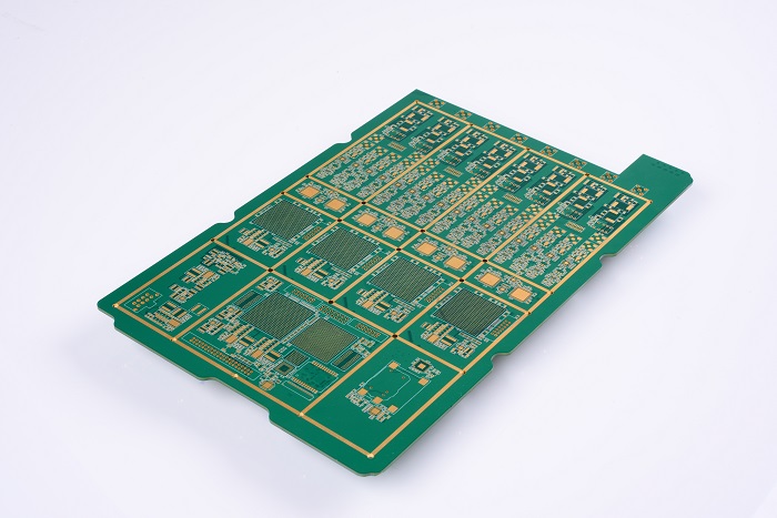
Printed wire width and spacing are important design parameters that affect both the electrical and electromagnetic compatibility of the PCB and the manufacturability and reliability of the PCB.
The width of the printed conductor is determined by the load current of the conductor, allowing for temperature rise and adhesion of the copper foil. The width and thickness of the wire determine the cross-sectional area of the wire. The larger the cross-sectional area of the wire, the larger the current carrying capacity. However, the current flowing through the wire generates heat and causes the temperature of the wire to rise. The temperature rise is affected by the current and heat dissipation conditions. The allowable temperature rise is determined by factors such as the characteristics of the circuit, the operating temperature requirements of the components, and the environmental requirements for the operation of the machine. Therefore, the temperature rise must be controlled within a certain range.
The printed wires are attached to the insulating substrate, and the excessive temperature affects the adhesion of the wires to the substrate. Therefore, when designing the wire width, the load current required for the wires should be considered on the basis of the substrate with the selected thickness of the copper foil. The width of the printed conductor is determined if the allowable temperature rise of the wire and the adhesion of the copper foil are satisfactory. For example, for a copper foil having a wire width of not less than 0.2 mm and a thickness of 35 μm or more, when the load current is 0.6 A, the temperature rise generally does not exceed 10 °C.
The spacing of the printed conductors is determined by the insulation resistance, withstand voltage requirements and electromagnetic compatibility, and the characteristics of the substrate. It is also limited by the manufacturing process. The insulation resistance between the conductors of the surface layer of the printed board is determined by the spacing of the conductors and the parallel segments of adjacent conductors. The length, the insulating medium (including the substrate and air), the quality of the processing of the printed board, temperature, humidity and surface contamination are factors. In general, the higher the insulation resistance and withstand voltage requirements, the wider the wire spacing should be. When the amount of load current is large, the small distance between the wires is not conducive to heat dissipation. The temperature rise of the printed board with a small wire pitch is also higher than the plate with a large wire spacing. Therefore, in design, the wire and potential with a larger load current are applied. For adjacent conductors with large difference, if the wiring space permits, the spacing of the conductors should be appropriately increased, which is beneficial to both manufacturing and low-frequency interference of high-frequency signal lines.
When designing a printed circuit board, the appropriate trace width and trace spacing should be selected according to signal quality, current capacity and PCB manufacturer's processing capability. The following process reliability requirements should be considered:
1. According to the processing capacity of most current pcb manufacturers, the line width/line spacing is generally required to be no less than 4 mils;
2. There is no right angle turning point allowed at the corner of the line;
3. In order to avoid crosstalk between the two signal lines, the two lines should be pulled apart in parallel. It is best to adopt a vertical crossover method or add a ground line between the two signal lines.
4. The board surface wiring should be properly sealed. When the difference in density is too large, it should be filled with mesh copper foil;
5. The traces drawn from the SMT pads should be pulled out as far as possible to avoid diagonal pulls;
6. When the SMT pad leads are thinner than the trace width, the traces cannot be covered from the pad and should be routed from the end of the pad.
7. When the closely spaced SMT pad leads need to be interconnected, they should be connected outside the pad and not directly connected in the middle of the pad.
8. Should avoid crossing the wires between the fine-pitch component pads as much as possible, and it is necessary to cross the wires between the pads, and apply solder mask to reliably shield them.