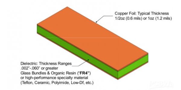
1.0 High frequency PCB material
When selecting a substrate for a high frequency PCB, it is particularly important to consider the variation characteristics of the material Dk at different frequencies. For the requirement of high-speed signal transmission or characteristic impedance control, Df and its performance under the conditions of frequency, temperature and humidity are mainly investigated.

2.0 Dk, Df and surface roughness
2.1 High frequency PCB requirements
1. Low Dk (Dielectric constant)
-Reducing the dielectric constant can increase the signal transmission speed
-Propagation delay=84.6×(εeff)1/2
2. Low Df (Dissipation factor)
-The frequency of the signal increases in proportion to the loss of strength. Therefore, high frequency PCB generally adopts Low Df material.
-Signal loss=27.3×(f/c)×(εeff)1/2×tanδ
3. Surface roughness of conductor
- If the signal frequency is higher, the skin effect is more obvious. Therefore, the surface of the signal transmission conductor depends on the flatness of the surface
-εeff: Effective dielectric constant
-tanδ: Dissipation factor
-f: Frequency
-c: Light speed
2.2 Dielectric constant: Dk or Er (ε)
1. Definition: How much ‘electrostatic energy’ can be stored per ‘unit volume’ of insulating material per ‘unit potential gradient’.
2. The dielectric constant (or permittivity) of the insulation should be as small as possible.
3. Now, the best dielectric constant for PTFE (Poly tetra fluoroethylene) at 1MHz frequency is 2.5, while that for FR-4 material is about 4.7.
4. The PCB can be regarded as a capacitive device. When there is signal transmission in the conductor, some energy will be accumulated by the PCB, resulting in transmission delay. The higher the frequency, the more obvious the delay will be.
2.3 Df (Dissipation factor)
1. Definition: A measure of the functional loss of alternating current
2. It is a property of insulating material (resin)
3. Dissipation Factor=Power loss/(E2) * (f) * (Volume x Constant)
2.4 Examples of Low Dk and Low Df materials
FR4

Special materials

2.5 Surface roughness of conductor
1. Conductor loss: The surface roughness of conductor causes the loss of signal energy to the resistance heating.
2. Skin effect:The current is concentrated in a thin layer on the outer surface of the conductor. The closer you are to the surface of the conductor, the greater the current density will be, while the current inside the conductor will be smaller. As a result, the resistance of the conductor increases, so does its lost power.
3. If the surface roughness of the conductor is flat, the better it is for the signal transmission of the conductor
4. Adhesion strength between PCB layers is affected by conductor surface roughness
5. The higher surface roughness of the conductor is, the more bonding area between the resin and the conductor is. And the intensity is also higher.
3.0 Copper foil
Copper foil is an essential material in the manufacture of high frequency PCB. Copper foil can be divided into two types, Electrodeposited copper foil and Rolled-wrought copper foil, depending on the manufacturing process.
3.1 Electrodeposited copper foil
Electrolytic copper foil is an important material in the manufacture of CCL, PCB and Lithium ion batteries. Electrolytic copper foil is described by some designers as the core of communication between electronic products' signals and power transmission.
3.2 Rolled-wrought copper foil
Rolled-wrought copper foil has a low surface oxygen characteristic, which enables its surface to be attached to a variety of different substrates (such as metals, insulating materials, etc.).
At the same time, it also has a wide temperature range. Rolled-copper foil is mainly used in electromagnetic shielding and antistatic at the same time. In the application of Rolled-wrought copper foil, it not only has excellent conductivity, but also provides electromagnetic shielding effect.
3.3 Comparison
Electrolytic copper foil: It is very cheap and can be made into different sizes. However, it is very malleable, which causes it to bend or break easily.
Rolled-wrought copper foil: It has a very high ductility and can satisfy with more electronic needs. On the other hand, its cost is high and its adhesion for the substrate is not very good.
The most important thing is that its width is limited.
3.4 Affecting factors of copper foil Dk
- Resin (Epoxy Dk:3-4)
- Glass fiber cloth (Dk:6-7)
- Resin weight ratio (Prepreg: gum content RC%)
4.0 PP(Prepreg)
Prepreg (Pre-impregnated Materials) takes Matrix steeping in to Reinforced Fiber, and it is the intermediate of composite materials. Compared with other materials, using the productive composite materials can improve peculiarity of strength,stiffness,corrosion resistance,fatigue,wear resistance, impact resistance, weight reduction and so on.
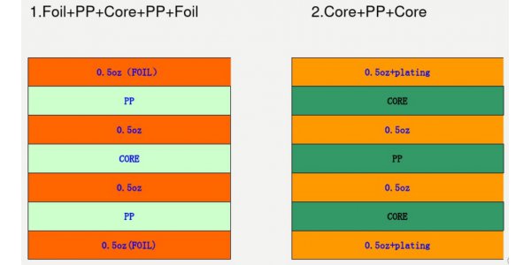
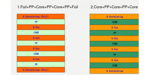
5.0 PP and core of stack-up
Four layers

Six layers


