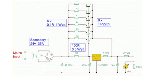
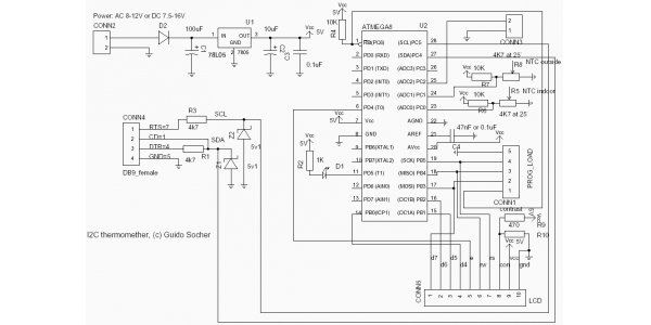
When we do electronic DIY production, it is inevitable to look at the pictures. However, for many novices, it seems that they always have a very chaotic feeling at the beginning. We only knew that we didn't understand the rules at that time.
Circuit diagram direction refers to the arrangement direction of each part of the circuit diagram from the initial input to the final output. The most common circuit diagram is from left to right, that is, the signal processing unit circuits are arranged from left to right. Some circuits are also arranged from top to bottom. Some complex circuit diagrams, for some reasons, in the overall compliance with the above rules, some circuits also have reverse arrangement, but usually use arrow symbols to indicate the direction of the circuit.

In general, the graphic symbols of circuit diagrams are only a basic figure, but we can change the orientation and drawing position of these graphic symbols according to specific needs in actual use. The orientation of component graphic symbols can be placed according to the drawing needs, either horizontally or vertically; it can be upward or downward; it can also be rotated or reversed in mirror image. Some components include several components, and centralized drawing and scattered drawing can be used in circuit diagram as required. Band switches can be drawn together and connected with dashed lines to indicate linkage; they can also be drawn near the circuit they control, and are represented by text symbols "s1-1", "S1-2" and "S1-3". Some components contain many independent units, especially the integrated circuit. Generally speaking, the simpler circuit adopts the centralized drawing method, and the more complex circuit adopts the decentralized drawing method.
The internal circuit of integrated circuit is generally very complex, including several units and many components, but in the circuit diagram, the integrated circuit is usually regarded as a component. Therefore, almost all circuit diagrams do not draw the internal circuit of the integrated circuit, but to hold or triangular frame to represent. Integrated operational amplifiers, voltage comparators, etc., are usually represented by triangular frames, whose vertex direction is the flow direction of signals. The voltage regulator, time base circuit, etc. are usually represented by rectangular frame, and each outlet is marked with pin number. The pin number can be marked outside or inside the frame, or on the rectangular frame. The pin number can be arranged in order or in disorder. Most of the other integrated circuits are represented by rectangular frames. Integrated voltage amplifier, integrated power amplifier, etc., can be represented by both triangular and rectangular frames, but amplifiers are represented by triangular frames, so the signal flow direction is more intuitive. Digital integrated circuits are usually represented by logical graphic symbols, such as gate circuits and flip flops. At present, other digital integrated circuits are still more represented by rectangular frames, and the logical function text symbols of the pins are marked.

The connecting wires between components are represented by solid lines in the circuit diagram. There is a dot at the intersection of horizontal and vertical wires, indicating that the two wires are connected together. There is no dot at the intersection of two wires, which means that the two wires are crossed but not connected. The simplified drawing method can be used for connecting wires. When the two ends of connecting wires are far apart and there are many graphic areas in the middle, the drawing method of interruption and marking can be adopted. The mechanical connection between some components is shown on the circuit diagram with dotted lines. When the dotted line connects the potentiometer RP with the switch s, it means that the power switch is controlled by the rotary axis of the volume potentiometer, and they are a linkage potentiometer with a switch.
Usually, the positive power lead in the power line or dual power supply is arranged above the component, and the negative power lead in the ground wire or dual power supply is arranged below the component. In general, the grounding symbol is led down, but sometimes it can be led up, left or right for the requirement of drawing layout. More complex circuits often do not connect all ground wires together, but with isolated grounding symbols instead. In general, the circuit diagram does not draw the power lead of the integrated operational amplifier to predict the digital integrated circuit, because this does not affect the circuit analysis function, but the power supply lead can not be forgotten when analyzing the power supply circuit and actual production.
