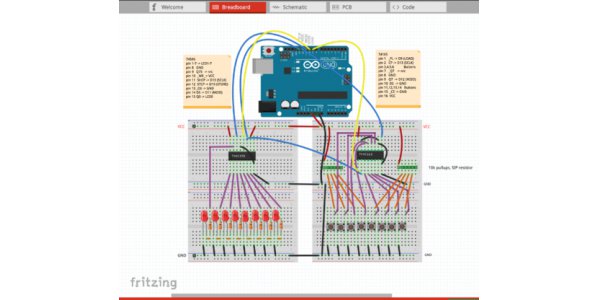
1.PCBWeb Designer
Pcbweb is a free CAD application software for designing and manufacturing electronic hardware. It uses fast and easy-to-use linear tools to design multi-layer schematic diagram, uses copper clad and DRC detection to plan multi-layer circuit boards, and embeds bill of materials. The designer of Pcbweb is one of the most functional editors on the network, and it can also be used for free. The software has an impressive lineup of tools, including schematic capture (placement of components, wiring / networking, annotation, etc.), PCB (placement of components, wiring, design rule checking, etc.) and parts Editor (create / define components, add symbols, etc.), in addition, it also includes the BOM function. The BOM manager integrates Digi-key, which allows users to assign a number to each individual component on its PCB. The number will be displayed through the BOM to facilitate purchasing. This software aims at efficient production.
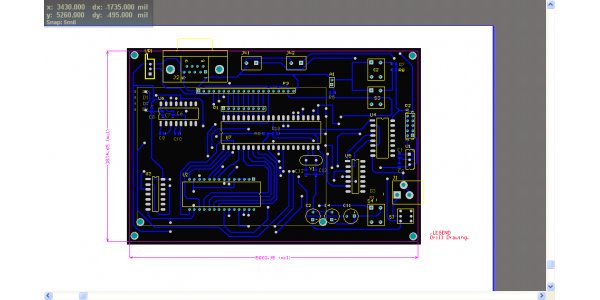
2.ZenitPCB
The platform provides a series of free software to help users design their own PCB. Zenticapture allows users to quickly and easily design schematic diagrams using a simple tool set, which allows users to place components (component symbols) through orthogonal locking and pin capture. Once the schematic (in the form of diagrams) is complete, they can be ported to ZenitPCB. Zenitpcb is an excellent PCB design software, can make professional circuit board, CAD module is flexible and easy to use, can quickly realize the design project. With zenitpcb, you can create a project from a schematic or from the layer itself. Zentipcb is a CAD based program that allows users to import net-list files and visualize their diagrams. The layout editor provides the function of importing components directly from the library by using cursors, and supports single-sided and double-sided boards according to different requirements.
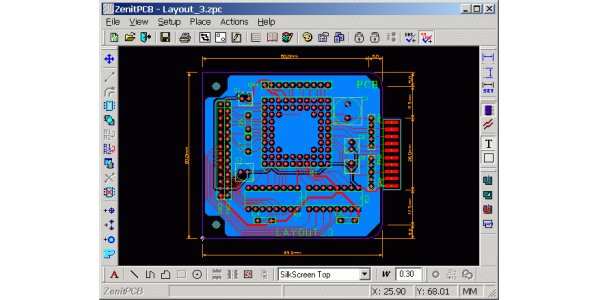
3.DesignSpark PCB
One of the most easily understood electronic product design software in the world, easy to learn and easy to use. This software can greatly shorten the time from concept to product, and its software engine enables fast access to schematic and PCB layer design. The PCB platform of designspark is another widely used PCB editing tool for EDA applications. Designspark PCB provides the function of schematic editing, while PCB wizard is used to improve schematic diagram, and auto router can complete automatic wiring between components. However, the software does have some points to pay attention to. For example, this software is very resource intensive. If the project does not exist on the same computer, problems may occur. In addition, some functions must be unlocked after the user has registered, and the worst thing is that the software will display advertisements.
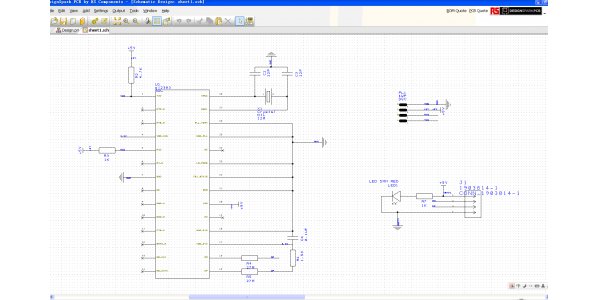
4.TinyCAD
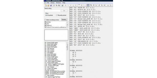
Don't underestimate the software because of its name. This software provides all functions of PCB design and wiring design. This is a help to draw circuit diagram software, it helps to complete your project from symbol library, simplify work project and design. It can also be used to publish the drawn circuit diagram by copying, pasting to word document or storing in PNG image format. The software contains 42 libraries with 755 symbols, including digital logic gate circuits, electron-mechanical components and even micro-controllers. Moreover, each component can be edited, and users can even add their own component symbols. Tinycad supports a variety of netlist formats (Eagle SCR, pads-pcb, XML, etc.) and can also generate spice netlist.
5.Osmond PCB
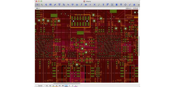
This is a very flexible PCB design software, it runs on the Macintosh. Many outstanding features include: virtual infinite board size, number of layers, number of components, support through holes and surface mount components. Osmond PCB is a Mac oriented PCB editor. It is from Osmond PCB. It allows users to design PCB of almost any size and shape, and can make as many layers as you want. The software can design wiring with spatial resolution as low as 10 nanometers and at any angle, and supports English and metric units. Osmond also allows users to move and re-position components, connect / route / modify paths, and use the library it contains to design PCB labels. The software also supports Lua script support, which can generate Gerber (rs-274x) files and Excellon demo files. This is a luxury for a free software.
6.BSch3V
Schematic design based on windows. "Bsch" comes from the abbreviation of "basic schematic". In order to simplify the operation, it has only basic functions. Those who don't want unnecessary functions and only need the most basic functions can try suigyodo's bsch3v schematic capture package (where bsch represents the basic schematic schematic schematic). The PCB editor allows users to design single-layer, double-layer, or even four-layer PCB, with a design area of 30mm2. It also has a component library, a component list generator and a netlist generator. Users can also use two other software to enhance the functions of bsch3v, including SmdICpad (used to obtain QFP, PLCC, SOP data) and polygon (copper storage area).
7. Cometcad
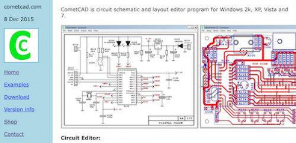
Cometcad is another excellent example of free software platform, which provides an electronic circuit schematic editor and a PCB wiring editor. Only this software only supports windows platform. Cometcad electronic circuit schematic editor supports multi-pages schematic diagram, symbol rotation, parts list and netlist schematic output. The PCB layout editor provides almost all the functions mentioned above (component library, double sided PCB, etc.), in addition, it also has the function of outputting cam files, and can be used to design rectangular various PCB boards.
8.Kicad
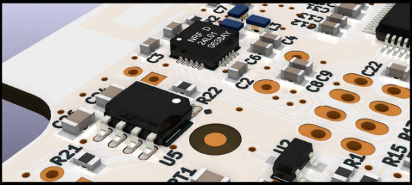
One of the most popular free PCB editors on the Internet is Kicad, an EDA tool similar to Fritzing. This software provides the function of virtual environment at every stage of the design process. The components include eeschema (schematic editor), Pcbnew (printed circuit board editor), gerbview (Gerber file viewer) and CvPcb (for component associated path selector). In addition, there is a built-in BOM manager, which allows users to mark the BOM and calculate the cost conveniently. It can be released on the GPL and the electronic circuit board. It is very suitable for everyone working in the electronic design industry, supporting up to 16 layers of schematic and circuit board design.
9.gEDA
It is used in circuit design, schematic acquisition, imitation, replication and production. At present, Geda project provides a set of mature software for free electronic design application, including schematic drawing acquisition, attribute management, BOM list, layer management, etc. Although in fact most PCB software runs on Windows based computers, there are also some designed for Linux users, including Ales Hvezda's Geda project, which provides a collaborative open source EDA tool. The collaborative part refers to the continuous efforts of collaborative developers to develop and update the Geda toolkit, including the schematic capture and netlist platform circuit design, PCB layout design and optimization, and Icarus Verilog (a hardware description language for analog electronic systems).
10.Fritzing
This is a very interesting open source design software, for designers, artists, researchers and amateurs, can creatively design electronic products. It can help understand electronic circuits, archive projects, and even prepare for production. Fritzing platform is not just a simple PCB editor, but its purpose is to create their own design for makers and hackers. The purpose of its design is to enable users to realize their own design based on Arduino micro-controller and create PCB wiring that can be used for production. Once the user has designed an actual circuit on the breadboard, it can then be transferred to the editor, which contains three different project perspectives. The breadboard perspective allows users to drag and place virtual electronic components on the virtual breadboard. Schematic view is the formal expression of schematic diagram, which is the corresponding circuit on virtual bread board, but users can also edit it according to their needs. Finally, the PCB perspective allows users to place components on a virtual printed circuit board, which can then be used for production.
