What is the Wiring Rules between Components
Posted: May 14, 2022
By: Bonnie
What is the Wiring Rules between Components
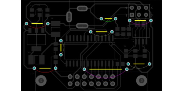
Crossed circuits are not allowed in printed circuits. For possible crossing lines, two methods can be used: "drilling" and "winding." That is, letting a lead “drill” through the space under other resistors, capacitors, or triode pins, or “wrap” from one end of a lead that may cross, how to make the circuit complicated in special cases. Allow crossover with wires to solve cross-circuit problems.
Introduction to wiring rules between components
1. Resistors, diodes, tubular capacitors and other components are installed in two types: "vertical" and "horizontal".Vertical means that the component body is installed and soldered perpendicular to the circuit board, which has the advantage of saving space. Horizontal means that the component body is parallel to the circuit board and is mounted and soldered. The advantage is that the mechanical strength of the component installation is better. For these two different mounting components, the component pitch on the printed circuit board is different.
2. The ground points of the same level circuit should be as close as possible.
And the power supply filter capacitor of this stage circuit should also be connected to the ground point of this stage. In particular, the grounding points of the base and emitter of this level of transistor should not be too far away, or the copper foil between the two grounding points will cause interference and self-excitation because of the long length of the copper foil. Stable and not easy to self-excitation.
3. The general ground wire must be arranged strictly in the order of high frequency-intermediate frequency-low frequency in order of weak current to strong current.
Don't just go around and connect randomly. Levels and levels would rather connect the long points, and you must also follow this rule. In particular, the grounding arrangement of the frequency conversion head, regeneration head, and frequency modulation head is more stringent. If it is improper, it will cause self-excitation and fail to work.
High-frequency circuits such as FM heads often use large-area enclosed ground wires to ensure good shielding effects.
1. High current leads (common ground, power amplifier power leads, etc.) should be as wide as possible to reduce wiring resistance and voltage drop, and reduce self-excitation caused by parasitic coupling.
2. Keep traces with high impedance as short as possible, and traces with low impedance can be longer, because traces with high impedance tend to flute and absorb signals, causing circuit instability. Power lines, ground lines, base traces without feedback components, and emitter leads are all low-impedance traces. The base traces of the emitter follower and the ground traces of the two channels of the recorder must be separated, each forming a path , Until the end of the effect is recombined, such as two ground wires connected to one another, it is easy to produce crosstalk, so that the degree of separation is reduced.
More resources:
Do you have any questions about the above-mentioned? Contact us now, we will reply to you soon.
Is the article useful to you?
No
Yes(
5
)
5
348
1
Share to: