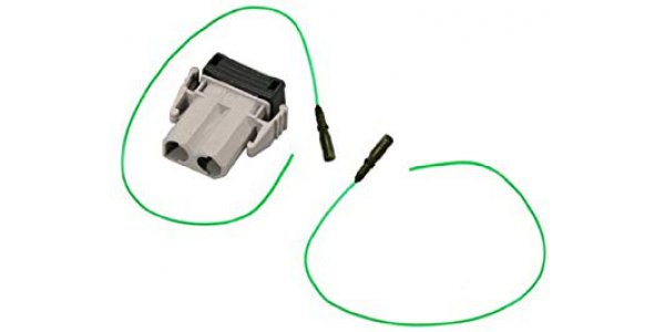
How to prevent the connector from falling out due to rude insertion by changing the process? For example, the SMD part is changed to a paste-in-hole process. That is, the original pure SMD part is changed to the traditional plug-in part manufacturing process, or the SMD solder foot + through-hole positioning column, and Paste-In-Hole (PIH) is used. PIH (Paste-in-Hole) is sometimes called PIP (Pin-In-Paste).

1. What difference does this make to the production line and design?
1.1. It is best to have tape-on-reel, so that you can use SMT machine placement / printing, and at least use hard tray packaging.Some parts manufacturers do not provide tape and reel packaging for new parts, but only tray packaging. If tape and reel packaging is necessary, some must pay the cost of mold opening. Another problem is that tape and reel packaging is usually more expensive than tray packaging, and it most often occurs on some connector parts.
1.2. The material of PIH parts must be able to withstand the high temperature of SMT reflow. Generally, PIH parts are required to be placed on the second side of the furnace. If it is only once, the current lead-free process requires at least 260℃ for more than 10 seconds.
1.3. Welding feet of PIH parts must not have kink and tight fit designs, otherwise the parts will be difficult to place on the board with the machine. If such parts are forced to be manually operated, it may cause because it is necessary to overvoltage the circuit board to insert parts, causing the circuit board to vibrate, and finally causing the already punched parts on the circuit board to be offset or dropped.
1.4. PIH parts must be designed with a flat surface on the top of the part so that the SMT nozzle can be sucked, or a piece of high-temperature air-proof tape can be pasted on it.
1.5. A gap / standoff of 0.2mm or more should be reserved at the junction of the soldering pin of the PIH part and the circuit board to prevent the occurrence of siphoning, causing tin overflow, and the problem of uncertain solder beads affecting the product function.
1.6. It is recommended that the height of the soldering feet of PIH parts exceed the thickness of the circuit board by 0.3 to 1.0mm. Too long is not conducive to picking and placing parts. Too short is likely to cause the risk of insufficient tin and easy to fall off, because most parts that will use the PIH process are external Connector.
2. How does changing pure SMD parts into PIH or SMD + PIH parts affect the manufacturing process and products:
1.Man-hours: There should not be much difference between the two parts.2.Cost: The cost of PIH parts may increase compared to pure SMD, because there are more perforated PIN feet.
3.Clearance between SMT parts:
The clearance requirement for hitting PIH parts is better than 1.5mm, while pure SMD parts only need to be 1.0mm, and some can even be reduced to 0.5mm. This is because the solder pin of PIH is relatively easy to deform, so the through hole will also be designed to be larger. Generally, the ratio of the diameter of the solder pin to the diameter of the through hole is 0.5 ~ 0.8, and the deviation of the punched part will be relatively large, so relatively large gap.
4.Heavy industry and repair:
Generally, PIH parts are more difficult to rework and repair than pure SMD parts, because the solder in the through holes needs to be removed when replacing the parts. Of course, it is also possible to consider destroying the entire part, but relatively difficult to rework PIH parts. The degree is still relatively high.
5.Circuit board space usage:
Because the back of the PIH part has the PIN pin protruding, the use space on the circuit board is relatively reduced.
6.Tin filling problem:
IPC-610 stipulates that the through-hole tin intake rate of the solder feet of through-hole parts must exceed 75%, but sometimes it is difficult to use regular solder paste printing to achieve such tin volume, so sometimes additional solder volume must be added.
3. Options for increasing solder volume: pre-formed tin sheet
The pre-formed tin sheet can have various shapes. It is basically a piece of tin made of solder. It can be used to make up for the shortcomings of insufficient solder paste due to the restrictions of printing on the steel plate. It is generally used for tape packaging and SMT processing machines.The advantage is:
1. Increase the amount of tin in the pin-in-paste process, so that traditional plug-in parts can have more complete solder and reduce solder holes.
2. Reduce the empty soldering rate and improve the solderability of poor flatness parts. Preforms can be placed on the solder pads and the amount of solder can be locally increased, so that the solder can contact the part feet to achieve the purpose of soldering.
Weakness is:
This is an extra cost, and the price of tape and reel is quite expensive. If you can, you can save bulk by buying bulk material to roll it yourself.
BTW: The pre-formed tin sheet can also be used for different purposes, such as directly in the middle of two metals as a contact slow charge. Or as a safety switch, when the temperature reaches the melting temperature, it will short-circuit and trip the power supply.
When the SMD part is changed to the plug-in PIH process, its solder strength will be stronger than that of pure SMD, and it can withstand greater or repeated external force insertion and withdrawal. Based on past experience, the bearing capacity can be about 1.5 times. Of course, it depends on the number of PINs and depending on the thickness of the PIN pin.
