Many PCB engineers have a headache in the face of CAD documents and do not know how to convert them into Gerber format files. In fact, it is relatively simple to master the method. We need AutoCAD 2004 or above and CAM350 (9.5 is recommended). Before generating the Gerber file, several standards need to be set, but these are not necessary for ordinary PCB designers. The following is a brief description of these settings. It is also possible to generate Gerber files without this setting. First of all, the setting of PCB shape and dimension is generally mechanic1 and 2 layers. Secondly, the preprocessing of multiple original PCB files before generating Gerber file includes: adding PCB process edge; adding stamp hole; adding machine jack; adding positioning hole for patch, which can be added in PCB file normally; adding drilling description; adding dimension. Finally, set the origin, edit → origin → set, and then set the origin at the lower left corner of the board. You can also use the tools menu option.

1) Open the original CAD document file > fabricopupus > Gerber files to get a preliminary understanding of the design layers. Select menu file - save as, select the directory where you want to save the file, and select DXF in the file type at the bottom of the window. It is recommended to select 2004 version and save.
2) Open CAM350 software, click file --- import --- DXF, find the DXF file just saved, select and open it. If the following window appears, it means that some graphics cannot be recognized. You can ignore it and directly click OK. Generally speaking, it is Chinese characters or other complicated lines that cannot be recognized.
3) Next, the parameter setting window will appear. In this step, set the unit to metric mm and the scale to 1:1. Used to specify the units and format used in the output Gerber file. The unit can be metric (millimeters) and English (inches); 2:3, 2:4, 2:5 in the format column represent different data precision used in the file, where 2:3 means that the data contains 2 integers and 3 decimal places; correspondingly, the other two indicate that the data contains 4 and 5 decimal places respectively. The designer chooses according to the unit precision used in the design. Of course, the higher the accuracy, the higher the requirements for PCB manufacturing equipment. Selecting units: inches, format: 2:5; normally, our precision requirement is not very high, after setting, click OK.
4) Set the layer to generate the Gerber file. Select the layer to generate Gerber file in the left "plot" list. If you want to mirror a certain layer, check the corresponding "mirror" image option; in the right mechanical list, select the mechanical size information to be loaded into each Gerber layer. If mechanical 1 on the left is checked, it will be displayed in single layer in photo file GM1. Check mechanical 1 on the right, and mechanical layer information will be added to each layer, that is, border layer. When the "include unconnected mid layer pads" item on the unconnected intermediate signal layer is selected, it is drawn in Gerber that the pad is not connected with the isolated pad on the intermediate signal layer. This function is only enabled when Gerber is output from PCB file containing intermediate signal layer. First select include unconnected mid layer pads, and then click the mirror layers drop-down menu all off to close all mirrored layers. In fact, it is turned off by default. Finally, to check that you don't lose layers, click the "plot layers" drop-down menu use on to select the layers used, or click the box under plot to select the layers to export. Remember that the right mechanical layer is not selected (second output).
5) Leave the default settings in "drill drawing". Both aperture and advanced adopt the default mode. Select embedded aperture [RS274X] "embedded aperture (RS274X)" and check the box. The system selects it by default. The aperture is automatically created when the Gerber file is generated. If this option is disabled, the aperture table on the right will be available and the designer can load the appropriate aperture table. Advanced sets various options related to photo film. In this setting page, the film size and frame size, zero character format, aperture matching tolerance error, position of sheet on film, generation mode of production file and plotter type are set.
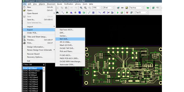
6) After setting, left click the "OK" button to output for the first time (the generated *. Cam cannot be saved). In the PCB file environment, file → fabrication output → NC drill files to export drilling files.
Enter the NC drill setup interface, and the option settings should be consistent with the advanced options settings of Gerber setup. Click the "OK" button and click the "OK" button in the pop-up "import drill data" input drilling data interface to output the second time. Generate drilling files. In addition, it can be said that the output is the third time, and then enter Gerber setup, file -- > fabricopupus -- > Gerber files.