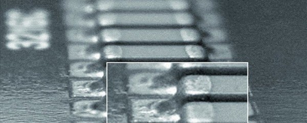
1. SMT solder joint quality and appearance
How to ensure the quality of solder joints has become an important issue for high-precision placement. As a soldering bridge, the quality and reliability of the solder joint determines the quality of the electronic product. That is to say, in the production process, the quality of the SMT finally manifests itself as the quality of the solder joints.

(1) Complete and smooth shiny surface;
(2) Appropriate amount of solder and solder completely cover the soldered parts of the pads and leads, and the component height is moderate;
(3) Good wettability; the edge of the solder joint should be thin, the wetting angle between the solder and the surface of the pad is preferably less than 300, and the maximum is not more than 600.
2. SMT appearance inspection content:
(1) Are there any omissions?(2) Whether the component is misplaced;
(3) Whether there is a short circuit;
(4) Whether there is virtual welding; the reason for virtual welding is relatively complicated.
3. Judgment of Welding
3. 1. Use special equipment for online tester for inspection.3.2 Visual inspection or AOI inspection.
When it is found that there is too little solder solder, poor solder wetting, or there is a gap in the solder joint, or the surface of the solder is convex, or the solder is not compatible with SMD, etc., it is necessary to pay attention, even a slight phenomenon can cause hidden dangers Immediately determine if there is a problem with batch soldering. The method of judgment is: see if there are more solder joints at the same location on the PCB. For example, it is only a problem on individual PCBs. It may be caused by scraping of the solder paste and deformation of the pins, such as the same location on many PCBs. Both have problems. At this time, it may be caused by bad components or defective pads.
4. Causes and Solutions of Welding
4. 1. The pad design is defective. The existence of through-holes in the pad is a major defect in PCB design. Do not use them unless they are used. The through-holes will cause the loss of solder and cause insufficient soldering. The pad spacing and area also need to be standard-matched.4. 2. PCBA board has oxidation phenomenon, that is, the pads are not shiny. If there is oxidation, the oxide layer can be removed with an eraser to make its light reappear. The PCB is wet. If it is suspected, it can be dried in a dry box. The PCB is contaminated by oil, sweat, etc. At this time, it should be cleaned with absolute ethanol.
4. 3. For PCBs printed with solder paste, the solder paste is scratched and scratched, so that the amount of solder paste on the relevant pads is reduced and the solder is insufficient. Make up in time. The method of filling can be made up with a dispenser or a bamboo stick.
4.4 SMD (Surface Mounted Components) is of poor quality, expired, oxidized, deformed, causing false soldering. This is the more common reason.
(1) The oxidized elements are dull. The melting point of the oxide increases. At this time, it can be soldered with 300-degree degrees of electrochromic iron plus rosin-type flux, but SMT reflow soldering with more than 200 degrees, plus the use of less corrosive no-clean Solder paste is difficult to melt. Therefore, oxidized SMD is not suitable for reflow furnace welding. When buying components, be sure to see if there is oxidation, and use them in time after you buy them. Similarly, oxidized solder paste cannot be used.
(2) Surface mount components with multiple legs have small legs and are easily deformed under the influence of external forces. Once deformed, false welding or lack of welding will definitely occur. Therefore, it is necessary to carefully check and repair in time after welding.
5. How to calculate the SMT chip price?
SMT patch price calculation is currently in the almost transparent stage, and the algorithm for how much is one point is simple. But first, the concept of "dot" needs to be clarified. Different companies use different algorithms, but for a PCB board, the final SMT chip cost is the same.The main purpose of SMT chip is to mount the chip components on the PCB pads. Some companies calculate one pad as a point, but there are cases where two pads are counted as one point. This article takes the pad calculation as an example. You only need to count the number of pads on the PCB. However, some special components, such as inductors, large capacitors, and ICs, need additional calculations. The specific experience is as follows: For example, the inductance can be counted as 10 points. , IC is folded in half according to the number of pins (for example, a 40-pin IC counts as 20 points). According to the above method, the total number of solder joints of the entire PCB can be easily calculated.
The next step is to determine the unit price of the solder joint. At present, the unit price of solder joints varies, which depends on the difficulty of SMT processing and the requirements and capabilities of SMT manufacturers for the quality control of the chip. Often the price is cheap, there may be no testing link, no material inspection link, it is difficult to guarantee the quality of the entire batch of SMT patches, and there will be great hidden dangers in the consistency and reliability of the product. Manufacturers with slightly higher patch prices will have quality control processes and can provide better delivery cycles and services.
